This is a device well known to most young parents - it enables them to hear their baby while it sleeps in the baby room, so that mom and dad can try to use those few precious moments to finish the daily routine walking on their thoes around.
There are many sorts of similar devices, some of them wireless and some yet more advanced models able to transmit not simply sound but live video as well. There is nothing wrong with hi-tech solutions to the ancient problem, but here is a simple and reliable way to overcome those few critical years of parenthood without much effort and expenses. The first circuit of this type that the author has built has been born out of his best man's frustration with the commercial gadget that simply didn't work as expected. The humble device described here served flawlessly.
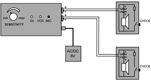
The idea was to amplify and transmit sounds of a sleeping (or not so much sleeping) baby using a pair of wires to a nearby living room. As can be observed in the diagram above, it is possible to connect two remote loudspeakers to the same amplifier at the same time. As there is no need for huge amount of power, a simple old mobile phone charger is able to supply the system with energy. A secondary source of power in the form of a set of four alkaline "AA" type batteries is also included in the design, which might prove useful in case of grid blackout, especially if it remains unnoticed by parents.
The circuit is based around a ubiquitous LM324 quadruple operational amplifier IC. One of the OP AMPs (A) is used as a microphone preamplifier and has a fixed voltage gain of 48x. This sound signal is then fed into two different branches. One branch is an output power amplifier formed out of OP AMP D and several medium-power transistors to which the input signal is fed via C9. Power amplifier too has a fixed voltage gain, this one being 11x. PA is a classical complementary pair design for which BC327/337 transistors are used in the output stage as they can withstand dissipation of up to 0.8W each, limiting the peak usable AF power to more than 2W, a solid figure for a baby monitor. The author decided to construct the hybrid power amplifier because it could be designed so that it would have far lower current consumption than inexpensive AF PA ICs, which was very important if the device was to be supplied by batteries. The overall AF gain is fixed to around 500x or 54dB which is more than enough to give a pair of 8-ohm loudspeakers enough oomph (or rather, screams :) There is no volume control as that proved to be unnecessary in practice - the aim of the design was not to enable parents to enjoy baby sounds but instead to be tormented by them.

The second branch to which the signal from the preamplifier A is fed is a squelch circuit made out of amplifiers B and C. This is the most interesting part of the design. If there is no signal going into the OP AMP B, there is no DC voltage at the output of the voltage doubler (C7, C8, D1 and D2) connected to it. This means that the inverting input of OP AMP C (pin 9) is at 0V while its inverting input (pin 10) is at approximately +1V constant reference voltage. This means that the output of the amplifier C is at logic high voltage, which is around +4V in this circuit. Via D7 that voltage is then fed to the noninverting input of the output power amplifier (pin 13) which makes it totally mute (its output is held firmly to 0Vdc).
On the other hand, if AF signal going from OP AMP B into the voltage doubler is of high enough amplitude so that more than +1Vdc gets to amplifier C inverting input (pin 9), it flips its output to low voltage (approximately 0.2V). This in turn causes D7 to stop conducting, releasing the output power amplifier from its muting grip. In order for this to happen, the amplitude of the AF signal coming out of the preamplifier A into the voltage booster B has to be above the certain threshold. Minimum threshold amplitude of received sounds can be easily adjusted over a very wide dynamic range because voltage gain of amplifier B can be controlled by feedback potentiometer P1. If P1 is set to the maximum resistance, voltage gain of the amplifier B is only 11x (21dB), which permits only relatively loud sounds (baby crying) coming from the microphone to deactivate the squelch. But if P1 is set to the minimum resistance, voltage gain of the amplifier B is as high as 470x (54dB) which means that even the tiniest sound (sobbing) caught by the MIC will be able to deactivate the squelch and find its way to the loudspeakers.
Diodes D11 and D12 serve to protect the power amplifier from overvoltages that might be induced in long loudspeaker wires. Components R16, C10, R22, C14, R25 and C15 shape the negative feedback in frequency domain and prevent the output amplifier from self-oscillating. The purpose of R23, R24 and D13 is to provide means for parents to manually deactivate squelch and check the sounds in baby's sleeping room whenever they find appropriate. This is done by closing the "VOX on" key built at each of the remote units i.e. loudspeaker boxes. By closing the contact, a 100 Ohm resistor gets connected to the loudspeaker line which passes approximately 5Vcc into it (negative loudspeaker line otherwise rests at 0Vdc due to resistor R24 pulling it to ground). This increased voltage is fed via R25 and D13 to noninverting input of the amplifier C, forcing it to immediately disable the squelch. Diode D3 protects the noninverting input from voltages higher than 4.7V.