Accurate temperature measuring originated in 16th century Italy. Over the centuries the technology progressed immensely so nowadays there are many kinds of temperature measuring devices - especially in electronics where temperature sensors range from variable resistors to computerised chips with numerical output. This article presents a simple circuit which performs very accurate measurements using inexpensive KTY series sensors, which can be tailored to specific demands via a dedicated open source Tcl/Tk PC application.
KTY sensor fundamentals
KTY type sensors are in essence variable resistors with positive temperature coefficients. There are two most frequently used series -
KTY81 and
KTY83, the former in TO92 plastic housings, the latter in DO-34 glass ones; electrically, there is very little difference among them. In both series, there are two subseries - the one with approximately 1 kΩ resistance, the other with approximately 2 kΩ at room temperature (25'C). Subseries can be determined by the first digit in the second part of the component marking, for example KTY81-210 is a sensor in TO92 housing with 2 kΩ nominal resistance. The remaining two digits ("10" in this example) define sensor resistance tollerance. Please refer to appropriate datasheets for more detailed explanations.
But why bother with such simple analog devices as there are fancy digital temperature sensors available on the market, one might ask. Well, there are several good reasons. Firstly, KTYs cost much less. This can be tollerated if a single sensor is to be used, but what if a whole array of them is needed? In such applications, the difference easily rockets to hundreds of $. Secondly, KTYs are much more rugged components. All they require is a somewhat constant power supply, but they easily tollerate voltage transients, current surges etc. which destroy digital electronics with no mercy. Furthermore, digital sensors are aimed to be placed at most a few decimeters (a feet) away from the µCPU while KTYs can be put hundreds of meters (yards) away from the measuring unit. Finally, maximal accuracy of digital sensors is very rarely better than 0,5'C which is nice but sometimes not nice enough for industrial applications, and there is nothing one can do about this. In contrast, KTYs can be made accurate to less than 0,1'C with very simple and inexpensive hardware such as the one presented here.
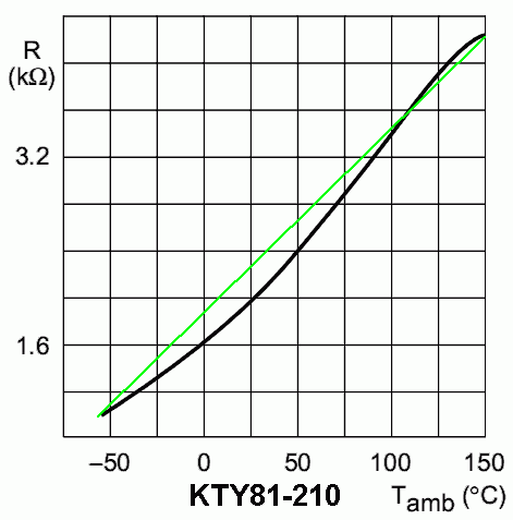
Philips, KTY sensor producer, gives accurate numerical data for each sensor type in the datasheets. When plotted grafically, it can be observed that a typical KTY resistance dependence on temperature is approximately linear, but not as much as one would expect. If one naively takes the curve as a straight line, the difference between the actual and the measured temperature easily exceeds 10'C near room temperature! Therefore, if KTY sensor is supplied by constant current source and then voltage on its contacts is measured, a kind of a nonlinear error correcting circuit is necessary to be used before displaying the voltage on a linear scale such as a galvanometer, A/D converter etc. Errors can also be corrected in software but that necessarily wastes precious processing power.
Fortunately, there is a way out. If KTY sensors are not powered by a constat current source, but by a constant voltage source using a constant resistor connected in series with it, it can be observed that for each sensor type there is a specific resistance that, inside a given temperature range, reduces the nonlinearities enormously! This is of course a too big struck of luck to be a mere coincidence - the autor of this article firmly believes that some dedicated component designers have spent many sleepless nights tweaking physical sensor characteristics to achieve this, but intriguingly Philips has never published this convenience in the datasheets.
So, basic idea is now clear: choose the sensor type and the operating temperature range, and then calculate the optimal linearising resistance value. Alas. Calculation is not at all straightforward as there is only a discrete numerical data set given in component datasheets i.e. no analytical formulas to deal with - not that it would make the process easier :) That is the reason why we have developed a small interractive PC applicaiton that enables visual estimation of sensor output voltage linearity if a particular linearising resistance is used. That program is presented on the third page of this article. But then, if the optimal resistance value is used, the output voltage range is at most a half of a volt or so between Tmin and Tmax - not really suitable for serious work. So we also figured out a simple operational amplifier circuit presented in the next page, that easily corrects this. And there is of course much more...