In many electronics applications there is a need to measure the frequency of the input signal. There are numerous ways to do so, from the simplest and least precise ones to noble methods of greatest accuracy utilised in the science of metrology. In this article we shall describe an inexpensive digital circuit that enables measuring signal frequency up to a few hundred kHz very linearly and very reliably.
The principle of linear frequency metering
In this article, by measuring frequency we will assume generating linear voltage proportional to fundamental input signal frequency, such that the shape of input signal pulses should have no influence on the final result.

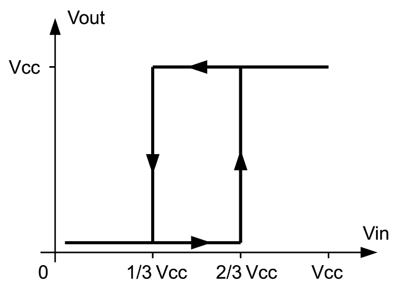
The first step in achieving the goal is converting natural analog signals, which may consist of pulses of arbitrary shape, into pulses of known and well defined shape. It should not be hard to understand that ideal pulse shape would like to deal with are plain and sharp digital pulses. The way to produce them is very well known - itís called the Schmidt trigger circuit, which in essence is a fast voltage comparator with relatively wide hysteresis between the two voltage margins to which it continually compares the input signal. There are not less than six such comparators in a single CD40106 hex-inverter IC with margins internally set to 1/3Vcc and 2/3Vcc, and we shall pick and use one of them as an input signal shaper (inverter ĒAď in the diagram below). If the signal has an amplitude high enough to alternatively pull gate A input below 1/3Vcc and above 2/3Vcc, at its output there will exist a train of digital pulses with nice sharp edges. If signal amplitude is less, it should be amplified first before being fed into inverter A; the amplifier needs only to be fast enough to respond to the highest expected signal frequency, while its linearity is of no concern as the signal fed to gate A is immediately turned into digital pulses anyway.
Now we reach the core of the problem - we need to find a way to convert these sharp pulses into DC voltage proportional to their frequency. A simple, reliable and very accurate method to do so is to form a pulse-width modulated signal (PWM), such that its mark-to-space ratio is proportional to input signal frequency. This may sound more complicated than it actually is. Imagine a mono stable multivibrator that generates a positive pulse of fixed duration each time it is triggered. If triggering occurs very rarely, average voltage at its output stays close to 0V. In contrast, if triggering occurs frequently so that positive pulses constitute the reasonable amount of the output signal mix, average voltage rises above ground; the more frequent the triggering, the higher the average voltage. In limiting case, i.e. when ftrig = 1/tpulse, output voltage is equal to the pulse amplitude as positive pulses follow each other rapidly with no periods of time when output is at 0V.
Linear frequency metering circuit
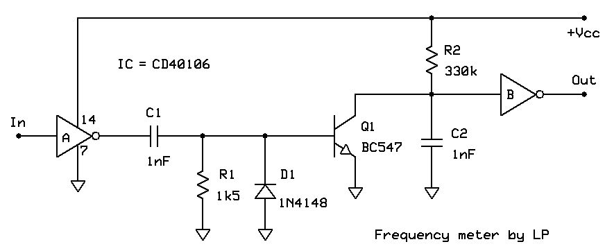
Since the signal observed at frequency meter input is periodic, it is not necessary to trigger the mono stable with each (rising and falling) pulse edge. It is in fact not even important which edge flavor we pick as a triggering source, as both falling and rising edges occur with the same periodicity. In the circuit presented here, rising edges of pulses going from input shaper (A) into mono stable multivibrator (B) do the triggering, producing positive pulses measuring +Vcc volts at its output. Because input shaper A is an inverter by its nature, this in turn means that the frequency meter as a whole reacts to input signal falling edges.

Triggering itself is done by discharging capacitor C2 sharply to 0V via transistor Q1. It is important to notice that duration of triggering pulses is added to the duration of pulses being generated, as output of inverter B goes to high state as soon as voltage at its input falls below 1/3Vcc and stays in that state as long as Q1 is active and then further as long as C2 voltage is still to reach 2/3Vcc. Therefore, triggering pulses should be as short as possible in order not to interfere with PWM output pulses (depending on time constant R2*C2) that carry the useful information. This is the reason that the time constant R1*C1 that sets triggering pulses duration is much less than the constant R2*C2. Diode D1 is there to catch inverse voltage spikes at Q1 base, preventing the degradation of its semiconductor junctions and further reducing the duration of triggering pulses. D1 is not essential for the circuit operation, but it is a good practice to keep it there.
And thatís it! If output voltage is to be measured by analog or digital voltmeter that respond to average DC voltage due to high mechanical inertia or internal electronic filtering, we donít need any additional components. But if output voltage is to be fed to A/D input of a microcontroller or similar device with fast response, it would be wise to add a simple RC low pass filter network to the frequency meter output.

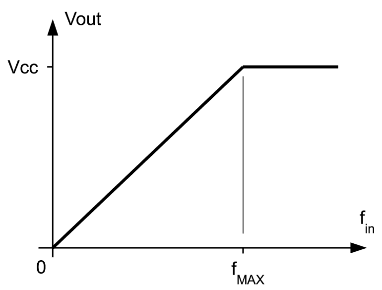
As can be seen in the diagram above, the transfer function of this simple circuit is amazingly linear. At 0Hz output is 0V, while it reaches +Vcc at a certain limiting frequency. It is useful to note that it stays nailed to +Vcc for even higher frequencies which is easy to understand - Q1 keeps discharging C2 so frequently that gate B input voltage simply never goes above 2/3Vcc causing its output to remain locked into logic high state. This is a very desirable feature as the information on actual input signal frequency for fin > fmax would be lost otherwise.
Limiting frequency fmax can be easily tuned to any practical value by setting the resistance R2. With that in mind, it would be practical to split R2 into fixed and variable part (10% of the calculated value) and fine tune the circuit response using stable signal source set to fmax. The only weakness of the circuit is temperature dependence of its response on temperature, caused predominantly by temperature instability of C2. Having this in mind, it is suggestive to pick a high quality capacitor for this task. Luckily, for capacitance values in range 1 - 100nF there are high performance components on the market for very reasonable price. Capacitor properties depend almost solely on dielectric material they are made of - the best ones are made of teflon film (expensive), followed closely by those made of styroflex (polystiren) and similar plastic materials. Please donít use ceramic or electrolytic capacitors except in the case of absolute necessity as they tend to behave rather poorly in circuits such as this one.

 The first step in achieving the goal is converting natural analog signals, which may consist of pulses of arbitrary shape, into pulses of known and well defined shape. It should not be hard to understand that ideal pulse shape would like to deal with are plain and sharp digital pulses. The way to produce them is very well known - itís called the Schmidt trigger circuit, which in essence is a fast voltage comparator with relatively wide hysteresis between the two voltage margins to which it continually compares the input signal. There are not less than six such comparators in a single CD40106 hex-inverter IC with margins internally set to 1/3Vcc and 2/3Vcc, and we shall pick and use one of them as an input signal shaper (inverter ĒAď in the diagram below). If the signal has an amplitude high enough to alternatively pull gate A input below 1/3Vcc and above 2/3Vcc, at its output there will exist a train of digital pulses with nice sharp edges. If signal amplitude is less, it should be amplified first before being fed into inverter A; the amplifier needs only to be fast enough to respond to the highest expected signal frequency, while its linearity is of no concern as the signal fed to gate A is immediately turned into digital pulses anyway.

