The purpose of this nice little circuit is well known to anybody who has ever had
to boil an egg or made a cup of tea on a stove - sometimes it is just too hard to
remember to get back to the kitchen and turn off the heat before it's too late.
In the first few years of XXI century the author of this article experienced an epidemic rise in such accidents among relatives, due to several mutually independent factors: he himself welcomed the advent of broadband Internet which made him prone to consciousness blackouts while checking ridiculous YT clips, his dad discovered Bubble_shooter and started experiencing similar symptoms, his sister married, gave birth to two beautiful daughters and soon turned into the worst case of daylight sleeping disorder ever seen in history, his grandma simply got 80... Even among coworkers the situation was not much better - gamers often fond going to bathroom too distracting, not to mention nuisances such as turning off the heater and preventing house fire, while conspiracy theorists perhaps did not but had a few scapegoats to blame for any foolish accident anyway. So something had to be done.
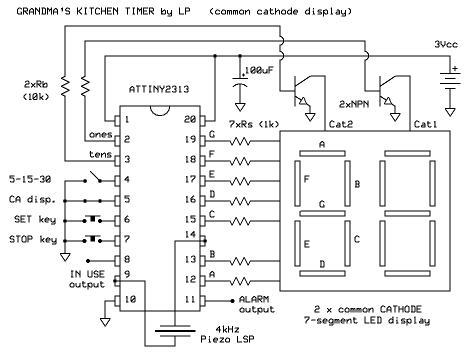
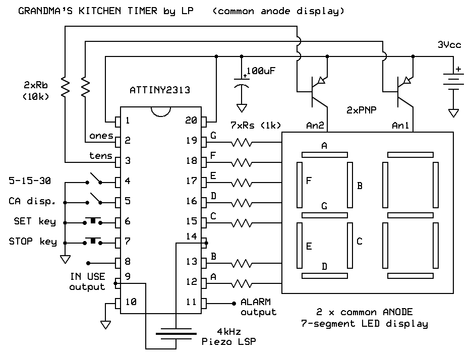
The circuit described here is probably as simple as it gets for a timer with 7-segment LED display. It consists of an inexpensive ATTINY2313 microcontroller, a Piezo beeper, two push buttons, two 7-segment digits and a few resistors to limit LED currents. The timer starts counting down to zero from the number of minutes set by the “Set” key. After the time runs out, it starts generating loud beeps through the small resonant Piezo loudspeaker (i.e. “passive beeper”). The user can turn off the timer by pressing the “Stop” key at any moment.

Two decimals of the display are multiplexed in order to spare IC pins. This means that both “A” pins of two digits are connected in parallel, so are the two “B” pins and so on, while each of the two common (anode or cathode) display pins has its own driver transistor. Software permits an easy way to adjust output pin operation so that one can use either common anode (CA) or common cathode (CC) display type in a device. In order to do so, there is no need to mingle with the software commands, but all one needs to do is, before connecting the circuit to the batteries, to connect pin 5 of the controller to circuit ground if common cathode display is to be used, of to left it unconnected otherwise. In addition, CC display needs two NPN transistors for mutiplexing, while CA type needs two PNPs. Both can be of any low power sort, for example BC547/557 as well as their SMD counterparts BC847/857 work O.K.

Piezo loudspeaker is connected to two outputs of the same ATTINY 8-bit timer in order to produce loud tones. These two pins operate in opposite phase which means that the effect is the same as if the loudspeaker was connected to a bridged power amplifier - AC voltage at loudspeaker pins is twice higher meaning that the generated power is 4 times higher than if one of the pins were connected to circuit ground. This is very useful as the circuit is powered by a low voltage battery. If one finds beeping sounds insufficiently loud, one can add the third alkaline battery to the supply, and remember to pick at least 2k2 or similar resistors with resistance higher that the value denoted in circuit diagrams for limiting multiplexed LED display segment currents to safe value.
An interesting feature of the timer is its ability to let the user to adjust the countdown time period in two ways. It can be adjusted either in discrete 5 - 15 - 30 minute steps, or from 1 to 60 minutes continually with a constant one minute step. The former is more appropriate for elderly persons not so familiar with “talking” to digital gadgets, while latter is more precise and certainly more interesting to play with for younger generations. The preferred means of timer adjustment can be easily set by connecting pin 4 of the IC to ground (continual 1 to 60 minute operation) or leaving it unconnected (discrete 5 - 15 - 30 steps).


