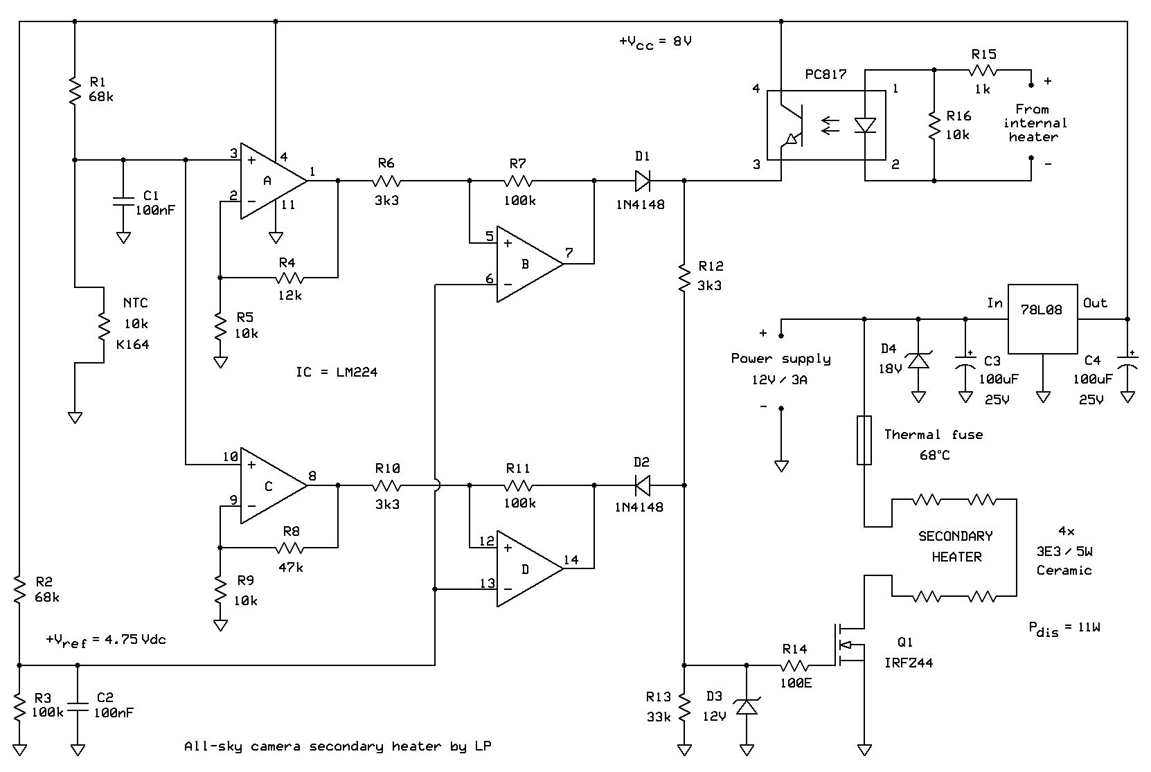
Secondary heater electronics
In essence, control circuit consists of two independent thermostats that use the same NTC temperature sensor. The first thermostat is built using operational amplifiers A and B. If sensor temperature is below +5°C, resistance of the NTC is high enough so that output voltage of the amplifier A is above +Vref (4.75V) which makes the amplifier B (that operates as a noninverting comparator with a small hysteresis) to produce logic high voltage. Via diode D1 it is then OR-ed with the output signal of the optocoupler, so whether or not the primary heater is on, the output transistor Q1 and the secondary heater it controls are on.

If temperature rises above +5°C, output of amplifier B turns low. This lets the primary heater control the operation of the secondary one. This is true if temperature is still below +35°C, as only under that condition amplifier (comparator) D output is high and diode D2 prevents it from interfering with the signals coming from either the optocoupler or amplifier (comparator) B.
If temperature rises above +35°C, resistance of NTC sensor gets so low that output of the amplifier C falls below +Vref forcing output D to turn low. This pulls any possible signals coming from the optocoupler via resistor R12 to ground, preventing Q1 to turn the secondary heater on. Thus the secondary heater cannot be turned on if temperature is higher than the safety threshold.
It is useful to note that both thermostatic circuits (A+B and C+D) use the same sensor and in the same way, the only difference between the two being higher DC voltage gain of the amplifier C (set by resistor ratio (R8 + R9)/R9) compared to that of the amplifier A (set by the ratio (R4 + R5)/R5). NTC resistor is chosen as a sensing device because, despite it being nonlinear globally, if set properly it is very responsive to small temperature changes; as the temperature range of interest (5°C to 35°C) is rather narrow, this means that raw signal-to-noise ratio that the sensor produces is appreciably high and would not let external interferences spoil the measurement process. Integrated circuit that contains all four operational amplifiers is LM224 which is in all other respects identical to ubiquitous LM324 except that it operates down to temperatures as low as -40°C. This is of course essential having in mind the purpose of the circuit presented here.
A thermal fuse that opens permanently should the temperature surpass +68°C is added to the heater circuit as a safety device of the last resort. Should anything go really wrong with the control circuit or wiring so that the heater becomes latched permanently on, it will safeguard the plastic dome from reaching its doom. Zener diodes D3 and D4 serve to protect Q1 and voltage stabiliser 7808 from damages caused by overvoltage spikes that may occur due to nearby lightning strikes and other disturbances, which are actually quite common at locations such as the one our camera operates at.
Secondary heater and its control circuit borrow the power from the camera itself, as its external power supply unit is able to provide significantly more power (12V/3A) than the camera and its inbuilt primary heater require (0.6A max). This means that both primary and secondary heaters share the common ground, so we could actually get over without using the optocoupler; but we really did not want to give the slightest chance to voltage spikes to circulate around as the price of the camera is no joke. Should one have any doubts about whether nasty things might occur and propagate inside a digital circuit, it is really quite simple and inexpensive to toss in an optocoupler or two and divide the (electrical) potential mess into well behaved independent realms.

