Magical function X or...
Now that we have figured out an ideal response function, we need to synthesize it out of basic binary logic algebra. There are many ways to do this and if done correctly, all of them will produce exactly the same mathematically correct result. The criterion we are especially interested in is that the formula be as simple as possible (using as few basic binary logic relations) since that equates to the fastest execution and the least consumption of precious CPU resources. Note that we are able to use all sorts of function primitives such as AND, NOR, XOR etc. because each of them can be carried out by the CPU ALU in a single step. If we were to use different kind of hardware, for example GAL or FPGA ICs, we could be limited to NAND/NOR or some other restricted set of logic gates and the optimal synthesis reasoning could differ.
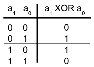
Luckily for us, there is a handy XOR (Exclusive-OR) binary function available in every CPU command list. Why is that important? Well, more experienced programmers are used to thinking of XOR not so much as of a logic function of AND or OR kind, but rather as of a gated inverter. This is well worth remembering as it is one of the trade secrets of digital gurus. To understand what the term “gated inverter” means, take a look at the next table. Note that if one of XOR inputs (e.g. a1) is in 0 logic state, XOR gate output is equal to the logic state observed at the other input (a0). But if input a1 is in state 1, then the gate output is equal to the inverted state observed at input a0. Therefore, one of XOR gate inputs can be taught of as the control input turning the gate into either a follower on an inverter of the signal found at the other (controlled) input. Because of the symmetry it is not important whether a0 controlls a1 or vice versa.

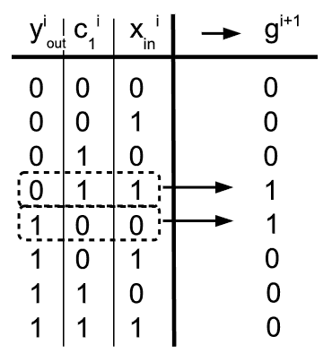
Ok, but why is this useful for debouncing? Remember that our reasoning went something like: “The output keeps the current state, except if ... when it inverts”. Doesn’t that sound like a call for an XOR? If we think about the current output state yiout as of the controlled input, all we have to do is to XOR it with the output of a cleverly designed intermediary logic function that takes raw input states sampled over a few previous time periods as its arguments (ci1 and xiin in this first example below). It should be obvious by now that such intermediary "flipping function" gi+1 must produce logic 0 everywhere except in case that at the same moment all (i.e. both) sampled inputs are either 0 or 1, and at the same time they have inverted binary logic state with respect to the current state of yiout output bit. See the next table:

Once both input bits become equal and of opposite binary logic state to the current output yiout, the output flips, and after that it requires both input bits to become inverted once more in order for it to flip again. Thus, if we find an effective way to construct the "flipping" function as depicted above, our goal is reached.
AND the final answer is...
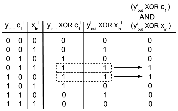
This final step might be a bit steep but we are almost at the summit. Take a look at the next diagram and observe that if we XOR yiout bit with either ci1 or xiin bits, we always get the result that is "vertically' symmetrical. This symmetrical response is of course the consequence of the symmetry in XOR function itself. Neither of the two partial responses is equal to the flipping function we seek, but the symmetry seems to be a good way to go. So, what happens if we AND those two results? Voila!

Let’s enjoy the moment and take a look at what we have achieved so far. Using only a few simple basic binary logic functions, we managed to form a kind of a low-pass filter that suppresses "high frequency" bouncing in signals that a microcontroller gets from the digital input lines. Not only is the method lightning fast, but it is able to filter many input lines in parallel, for no additional cost in processing time or other CPU resources.
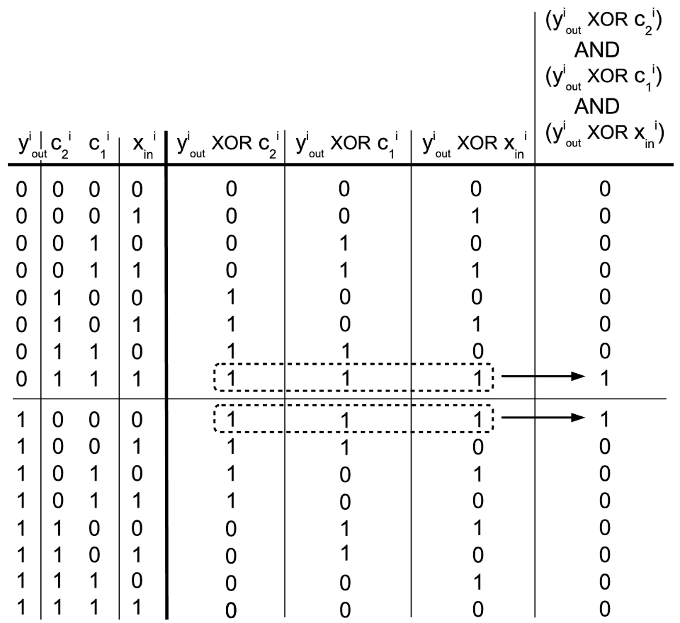
We will now bring this binary trip towards the finale by generalizing the method to filtering of arbitrary length, where “length” is the number of successive time intervals at which one wants to sample input lines. So far, we have limited our efforts to merely two input vectors ci1 and xiin, sampled at only two consecutive unitary time steps. But what if a more serious filtering is wanted? Following a good engineering practice we shall not try to reinvent the wheel, so let’s try to apply the very method that we have just developed to three input vectors (ci1, ci2 and xiin) instead of two:

Yes, everything seems to work well. Function depicted in the previous diagram will flip a certain bit position in the next output vector iteration yi+1out only if corresponding bit positions in all three input vectors have become inverted with respect to it. Nothing can stop us now from applying the method of induction and writing down a generalized form of the k-th order debouncing function:
yi+1out = yiout XOR [ (yiout XOR xiin) AND (yiout XOR xi-1in) AND ... AND (yiout XOR xi-kin) ]
If you feel inspired by the writing so far, you may come upon the idea to optimise the previous formula even further, following the footsteps of James Watt and George Stevenson - Thy shalt transform linear motion into circular and thus obtain thyself an engine! Of course, “linear motion” nowadays reads “a boring stretched equation”, while “to circulate it" means “to make it bite its own tail by wrapping it into a FOR-loop”.
But in practice, it is hard to imagine a situation in which debouncing key inputs using more than three consecutive input vectors would be really necessary, and consequently the three-step formula is the variant that the author of this article uses a lot in his own projects. The routine shall be able to flip its output at least approximately every 1/20 to 1/10 of a second in order for the device it is built in to be as responsive to human interaction as users expect it to be. This translates to input sampling + debouncing routine calls to be issued every 1/60 to 1/30 of a second. This is how it usually looks like in practice:
unsigned char inputLines[3];
unsigned char debouncedOutput;
.
.
.

// This function is called approximately each 1/60 to 1/30 sec.
void debounce(void)
{
    // Move previously sampled raw input bits one step down the line.
    inputLines[2] = inputLines[1];
    inputLines[1] = inputLines[0];

    // Sample new raw input bits from PORT_A.
    inputLines[0] = PINA;

    // Debounce output bits using low-pass filtering.
    debouncedOutput = debouncedOutput XOR (
            (debouncedOutput XOR inputLines[0])
        AND (debouncedOutput XOR inputLines[1])
        AND (debouncedOutput XOR inputLines[2]));
}
We will conclude this article by remarking that should one want to design a well behaved digital device, debouncing is necessary to be performed on all its digital input lines whatever their actual source and sampling method might be. For example, if an "X x Y" square array of mechanical keys is to be read out, raw input bits gathered using matrix multiplexing of raws and columns shall be put into a linear vector (a single binary variable of an adequate bit-length) first, then that vector shall be debounced, and only then shall nicely filtered output bits be used to control the device. The same goes with binary data transferred over long paralell digital lines etc. Happy flollopping!


