State diagram
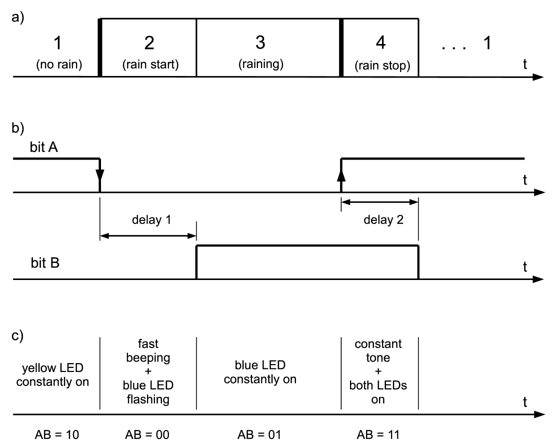
If we have a signal that carries information on whether it rains outside available, we need a means of indicating that information to the end user. What we want to construct is something similar to what one commonly thinks of “alarms” - a device which has some flashing lights on it, and which is able to generate loud beeping sounds. Since raining is not quite as alarming situation as a bank robbery, our indicator should make sounds only a few seconds after it has detected that rain just started or stopped, but should be silent in between. In other words, it should use sounds only to indicate “raining state” transitions. In order to indicate the current state of raining, it will use two LEDs - a blue one to signal “rain” and the yellow one to indicate “sunny” i.e. dry weather. We also want it to blink LEDs simultaneously with beeping, while they should stay on in other times, thus the user can take a look occasionally to check if anything has changed outside, but even without direct looking they will be promptly informed on transitions by beeping and flashing. We can draw a simple diagram to help us visualize what has just been said.

One can observe in a) that there are four distinct states in which the indicator unit can found itself. This suggests that only two state-defining bits are enough to uniquely control all other device functions. One of those two bits (bit A) is obviously the "raw" signal which the outdoors unit sends to indicate whether it currently detects rain or not. The simplest way to fabricate the second bit (bit B) is to make a delay circuit and connect its input to the first bit. This is depicted in b) in the previous diagram. As can be observed, this gives a unique binary representation not only of the current raining state, but also on the ongoing transitions in it. Then all we need to do next is to devise the rest of the circuit that will be able to respond to the two governing bits by turning LEDs on and off, by blinking them and by beeping. The actual operations which we want the indicator to perform in particular time intervals are denoted in c).
What's inside?
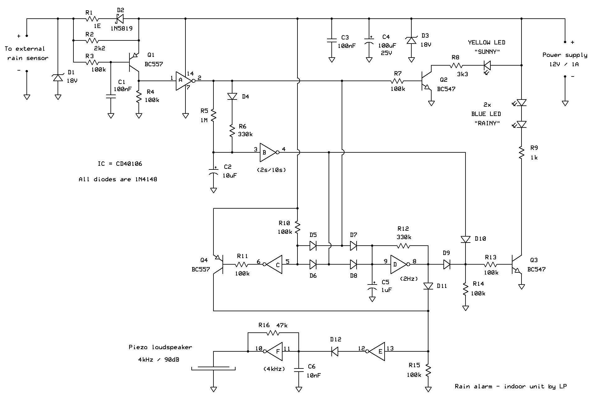
If we take a look at the circuit diagram of the indicator unit, we firstly observe the outdoors unit current sensor made of R1 to R4, C1, D2 and Q1. If more than 250mA flows through R1 and Schottky diode D2, voltage drop on two of them connected in series is high enough so that PNP transistor Q1 turns on and pulls gate A input to logic high (+12V). Other two resistors serve only to keep Q1 firmly in the off state when there is little or no current going into the outdoors unit (R2), and to limit Q1 base current (R3). C1 is there to prevent fast transients due to external interferences.

If inverter A input is logic low (no rain outdoors), its output (designated “bit A” in the state diagram) is logic high and via Q2 yellow LED is turned on. When there is rain, bit A is 0 and yellow LED is off. Gate B and a few surrounding components form a delay circuit that has been mentioned earlier. Whenever bit A changes, a certain delay must pass before C2 responds to that change as it takes time for it to charge or discharge through R5. Thus, changes in gate B output (i.e. “bit B”) always lag changes in bit A, and once bit B changes it takes the opposite value with respect to bit A. Components D4 and R6 make the two delay times (transitions from bit A logic high-to-low and from logic low-to-high) unequal. This is because we want annoying beeping that indicates the start of rain to last approximately 4 times longer than the calm constant tone that indicates that rain has just stopped. In times when it rains, bit B is high and that thanks to Q3 blue LED is constantly on.
With the two state-defining bits A and B thus formed, the rest of the circuit simply responds to them by flashing and beeping, meaning that as long as the two bits are in a particular state (for example AB = 00), the device does something (for example beeps and flashes the blue LED). We will now analyze how those signaling operations are implemented.
We have already explained the two “constant” cases i.e. when it does not (AB = 10, case ”1“) and when it does rain (AB = 01, case ”3“) for some prolonged time - either yellow or blue LEDs are then constantly on and there is no audio tone being generated. Now, what happens in transition times in which bits A and B take equal values? Let’s first consider the simpler case in which both bits are logic high (AB = 11), because bit A has turned 1 while bit B has still not turned 0 (case “4” = rain has just stopped). The first fact we can observe is that this is, thanks to diodes D5 and D6, the only case in which input of gate C is logic high. Consequently, this is the only case in which its output is logic low and Q4 is turned on. If that is so, then Q4 pulls input of gate E to logic high state, forcing its output to logic low. What this means is that, due to D12 orientation, gate F is now free to generate audible tone. Thus, as long as bits A and B are both 1, constant tone is generated in the Piezo loudspeaker. Since both A and B are logic high, this also means that both Q2 and Q3 are conducting, i.e. both yellow and blue LEDs are turned on. Constant tone and both LEDs on are interpreted by users as “Ok, the danger has now passed”.
The last case is the transition after rain has just begun i.e. AB = 00. Gate C is then logic high, so Q4 is off and it cannot make the oscillator (gate F) to generate tone. Both yellow and blue LEDs should also be turned off. But gate D now comes into action and changes everything. Due to the orientation of diodes D7 and D8, AB = 00 is the only case in which 2Hz oscillator formed out of gate D, C5 and R12 is not blocked. Since now it is free to do whatever it wants, gate D generates 0.5s/0.5s quadratic logic signal at its output. Through D9 this rhythmic signal is fed to Q3 which makes the blue LED flash. In addition, the signal is via D11 also fed to gate E input, which means that it alternatively enables and disables audio frequency oscillations of gate F, in synch with led flashes. Voila!
No part of the indoor unit is critical - although everything works fine with component values as depicted in the diagram, it is easy to change the default device behavior by tweaking the value of a resistor or two. For example, duration of “warning” transient interval (beeping + flashing blue LED) depends linearly on the time constant C2*R5. If one sets R5 to 2.2 MOhm and keeps the same value for C2 (10uF), beeping will be heard over more than 22 seconds. With that constant set, time constant C2*(R6 in parallel to R5) sets the duration of the second transient interval (constant tone + both LEDs on) - if equivalent resistance of R5 and R6 is for example 6 times smaller than R5 alone, the second interval will be 6 times shorter then the first one. Modulating frequency that makes sound beeping and LED flashing is set solely by the time constant C5*R12. Similarly, tone frequency depends only on the time constant C6*R16. It is advisable to set R16 carefully with the actual Piezo loudspeaker connected to the circuit as it is important to tune the frequency of the tone oscillator to the resonant frequency of the loudspeaker - tone volume can be easily more than 10 times higher in resonance than otherwise. It is also smart to pick block-polyester type capacitor for C6 because that will make tone frequency (and consequently its volume) stabile with respect to ambient temperature changes.
The whole indoor unit requires a single inexpensive CD40106 IC which contains all six Schmidt-inverter gates. If power supply voltage is kept to under 5V, then 74HC14 can be used with equal success. Despite being presented as a part of rain detector device, nothing stops readers from using this circuit as a handy gadget for indicating that the state of some important digital signal (for example door opening or closing) is changing, or that a certain important analog value (for example temperature) is reaching a critical threshold etc.
Some readers might find the style of indication that the circuit performs reminiscent to what a typical bed-side monitor (a TV-like hospital device that blips and draws pulsing lines) does in ‘80-ies action movies - if a wounded character’s pulse drops below the lower limit, suddenly an avalanche of beeping and flashing slides down the critical care unit corridor urging the staff to re-animate the protagonist so that he can later bring his vengeance to bad guys, get the most beautiful girl and live happily ever after... well, honestly, yes - of course we have been inspired by cult cinematography :)


