Negative Temperature Coefficient resistors
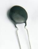
Thermostat circuit as presented on the previous page uses NTC resistor as a sensing element in order to control the operation of a small brushless DC fan motor. It has been built in order to prevent overheating of a power supply unit used in another project we carried out. NTC resistors are pretty old but still useful components - they usually take the form of a small disk shaped resistor which exibits steady decline in internal resistance while the surrounding temperature rises. What is important to remember is that resistance to temperature dependence of NTCs is very nonlinear so this components are not particularly suitable for taking precise temperature measurements. While
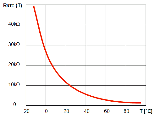
precise mathematical formulas for calculating NTC resistance versus its temperature do exist, for most practical applications it is sufficient to assume that NTC resistance falls 4% for each 1'C rise in temperature: R
NTC(T + 1'C) = R
NTC(T) * 0,96 . When plotted into a diagram, this formula produces a typical "decaying" exponential function, as can be seen below.
Sensing NTC resistance is often done by connecting it as one part of a voltage divider branch, such as is the case in this circuit. In order to achieve optimal performance, i.e. large enough sensitivity of divider output voltage versus NTC resistance changes, it can be advised to set the value of the biasing resistor (R4) to be equal to NTC resistance near the intended threshold temperature. For example, if we want our thermostat to switch the load at approximately 25'C and we picked an NTC which has 10 kΩ resistance at 25'C, then it will be wise to pick R4 close to 10 kΩ. This way one exploits a portion of the exponential curve with high slope, while DC voltage found at the divider branch output at threshold temperature is close to Vcc/2. As a consequence, this leads not only to maximising the dynamic range of the sensor circuit but also to rendering sensor voltage changes versus temperature fluctuations maximally flat in the region surrounding the threshold temperature - not essential for this particular circuit operation, but well worth remembering.
In order to make finding optimal component values for the simple thermostat circuit easy, we made a dedicated JavaScript calculator. Designers are expected to enter the resistance value at room temperature (25'C) of a particular NTC model they intend to use, threshold temperature in ['C], hysteresis temperature amplitude in ['C] and supply voltage value in [V].
It is assumed that inexpensive and ubiquitous LM358 dual operational amplifier will be used. In that case, supply voltage should not be higher than approximately 30V, but common values below 15V will give better circuit reliability anyway. Resistance R
7 should not be lower than 2,2 kΩ, which is enough to turn the output transistor T sharply on and off. As for the transistor, small signal BC547 and similar NPN models will suffice for loads up to 0,3A. If more output current is necessary, one should either choose a powerfull N-type MOSFET such as IRFZ44 or pick/design a
Darlington or
Sziklai transistor pair instead of T. Diode D serves only to protect the output transistor from reverse voltage spikes caused by switching off inductive loads such as motor windings and can be ommited if load one wants to control is resistive by its nature.
The circuit as drawn on the previous page turns on the load if temperature is above the threshold temperature. If one wants to design the circuit so that it turns on the load when temperature is below the threshold, all one needs to do is to swap positions of R3 and R4 (and consequently of R1 and R2).
If one wants to build a circuit that will react to some other physical property of the medium other than temperature, one should use the appropriate sensor type instead of an NTC resistor. As might be expected, the above JavaScript calculator is in that case of little help. For example, for sensing light intensity, one should use either a light sensitive resistor (expensive) or a phototransistor (cheap) in place of R
3. For sensing humidity, one can use either a
DIY probe or a commercial resistive sensor. The list goes on. What is important to note is that thanks to using the left half of the IC (A) as a voltage follower, input resistance that the circuit presents to the sensing voltage divider is very high. This enables using sensors with high internal resistances. In extreme cases, i.e. if sensor internal resistance is expected to be in MΩ range, the designer should consider substituting LM358 for an operational amplifier with CMOS inputs such as CA3240.