Opto-mechanical tilt sensor
Mechanical design of our sensor is depicted in the first drawing. It consists of a machined metal funnel and a steel ball put in it. If the sensor is in vertical position, the ball rests at the bottom of the funnel. When the sensor starts tilting, the ball stays in place as long as the tilt angle remains below the threshold limit. Once the tilt exceeds the maximum acceptable value, the ball promptly rolls out of its place causing a simple electronics to signal the alarm.
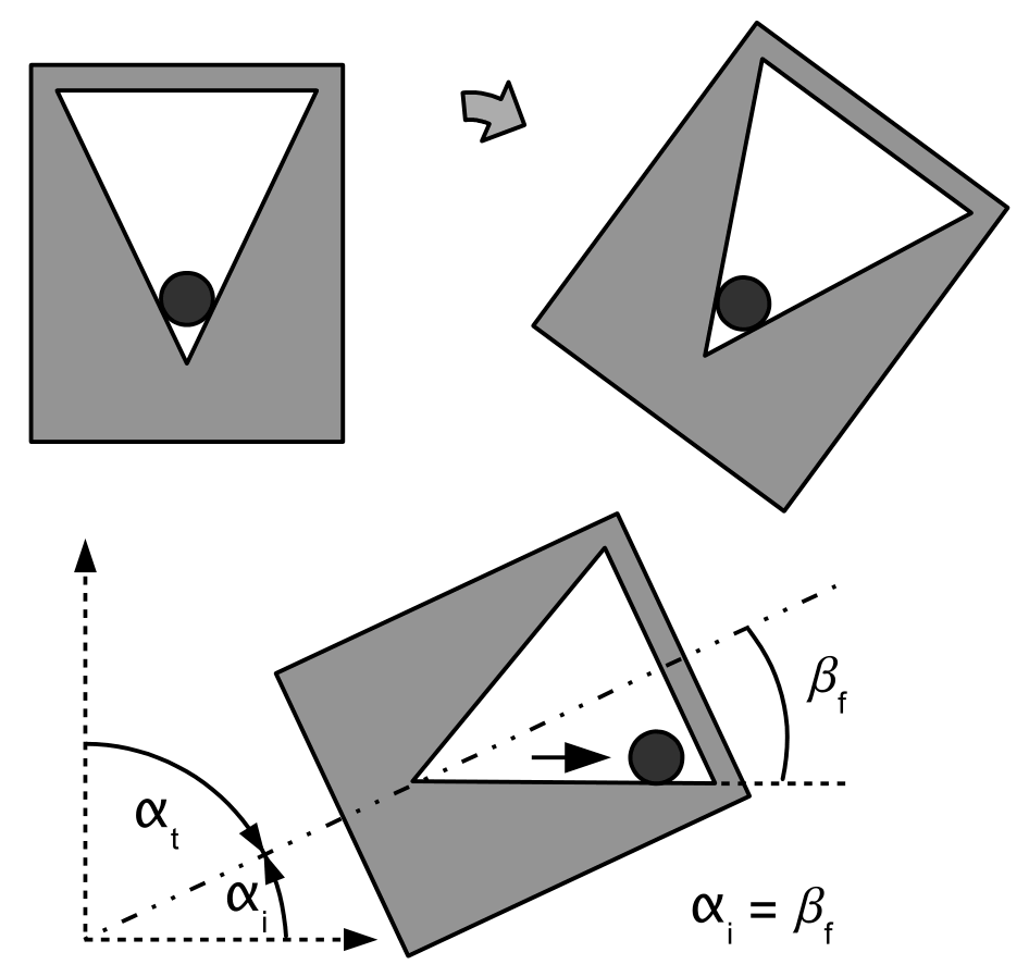
It is important to note that the threshold tilt angle is absolutely non dependent on the azimuth, because the funnel shape is rotationally symmetrical with respect to the vertical axis - to whichever point on the horizon one starts leaning the sensor, the alarm is sounded after reaching the very same maximum tilt.
By looking at the previous illustration, it is easy to conclude that the threshold inclination of the sensor (at) is equal to the angle that its funnel forms with respect to the central axis of symmetry (bf). Since a tilt angle is the supplementary of an inclination to the straight angle (ai = 90° - at), a shallow threshold tilt angle of 15° that we targeted called for lovely elongated sensor shape.
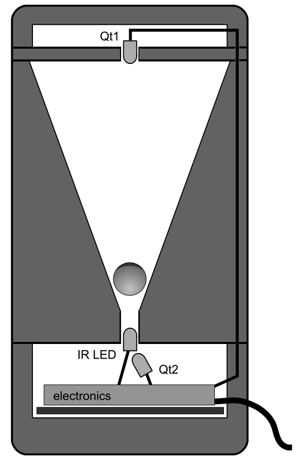
Without much doubt, we decided that the optimal method of detecting the missing ball is optical. The construction of the base funnel enables a light source (IR LED) to be put on the one-, and the photodetector (phototransistor) to be put on the other side of the gap. When the sensor tilts, the ball rolls out and the photodetector senses a sharp increase in light intensity. A reliable digital circuit implements this function.

The circuit is so simple that it hardly deserves a description. In case of tilt, phototransistor Qt1 pulls R5 towards +Vcc which makes Schmidt-inverter B to pull its output to GND. This turns off the output transistor Q1 and the drop in sensor output current is detected by the central controller of the telescope. Gate C is there only to force Q1 into conduction as soon as the sensor is powered up, because slow turn-on of the circuit might trigger false alarm in the telescope central controller (which by its nature needs to act rapidly to protect the telescope from misfortune).
The only quirk is that we need to be positively sure that the yet-not-tilted sensor is actually able to sense the tilt and that the alarm signal can then be fed into the telescope controller. This is the reason that we designed the circuit so that if everything is ok, Q1 conducts. This enables the controller to detect breaks in a cable that connects the sensory circuit to it and to stop the telescope, as otherwise in that case operators would be lulled into a false sense of security while there would be no way for the controller to sense and prevent accidents.
In addition, we need to be sure that LED is emitting photons as it should be, as otherwise Qt1 has no light to detect in case the ball roles out of its place. It is truth that IR LEDs are astonishingly reliable components and that we were not going to force it to nowhere near its full power, but sudden unexplained LED failures do occur in practice, so the second photodetector was added to the circuit with the aim of monitoring the LED health. Physically, the second phototransistor is mounted at the back side of the LED. While LED works Ok, there is more than enough light for Qt2 to remain saturated. But if the LED degrades over time or it suddenly stops emitting light, Qt2 photocurrent drops enough so that gate A input gets pulled to ground by R7. This makes gate A to turn its output logic high, and that signal is then OR-ed via D2 with the expected positive voltage that Qt1 generates in case of alarm. So if the LED stops working, sensor alarm is activated and telescope stops.