Very special sensors
When first faced with the task, we searched the net and gathered some interesting experiences from people who had done similar projects in the past. One of the more successfull seemed to have been the survey conducted for Giant Magellan Telescope which relied on very exotic miniature thermo-couples - an elegant solution but very expensive and almost impossible to replicate because the producer of those components had went out of business. Others used tiny resistive wires and that is what we decided to use as well. In order not to burden ourselves with extruding and mounting 10um thick platinum wires, we cunningly located miniature light bulbs and transformed them into fine sensors by very carefully smashing their thin glass baloons. Temperature coefficient of tungsten (wolfram) electrical resistance is +0.004403/K at 25°C which is actually higher than +0.003729/K for platinum.
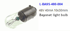
Our sensors should have had as little mass as possible so that they could respond to very fast changes in ambient temperature. We aimed at 100 Hz. This meant that wires should have been as thin as possible. At the same time, wire resistance should have been as high as possible so that we could get the highest intrinsic signal level on them - the higher the resistance through which one would push some reference constant current, the higher the changes in voltage readout were going to be. Put these two requirements together, and ideal light bulbs were the ones designed for as low operating current as possible, while at the same time for as high operating voltage as possible. In addition physcal dimensions of a sensor must not have been larger than the smallest air vortices we aimed at detecting i.e. approximately a centimter across. 48V/40mA model ulb pictured on the right seemed as a quite nice match. One can calculate that resistance of such filaments is 1.2 kOhm but that would be the case at nominal operating temperature of 3,500 K. At room temperatures the resistance is approximately ten times lower.
Differential amplifier circuit
The first diagram below represents the core of the instrument. It is a classic differential amplifier circuit formed by three operational amplifiers. U1 and U2 operate with relatively high DC gain because that way we can reach higher CMR ratio i.e. amplify preferentially the difference between the two voltages on their + input pins, while at the same time stay as much as possible immune to the absolute value of the common mode voltage. These amplifiers extract tiny variations of sensor voltages on the order of a few microvolts, so they need to be of highest quality. Luckily OP177 chips were easily available locally and very well suited to the task. In principle, we could have used dedicated "instrumentation amplifier" chip instead, but none of the available models could fulfill all the requirements: either the supply voltage was odd, or they could not operate below 0°C...

So we opted for a "discrete" solution. Although it does require more work on the part of designer and constructor, it offers some important advantages. We have to remember that sensors we decided to use are not perfectly matched with each other. In order to compensate huge variations that such discrepancies would introduce into the output signal after high amplification, we needed to put a so called "servo" negative feedback into the circuit. That is the purpose of amplifiers U3B and U3C in the full circuit diagram given below. U3B is an integrator that guarantees that common mode voltage at U1 and U1 outputs equals +2.5 V reference voltage by adjusting both sensor curents. U3C monitors the difference between the two outputs and slowly brings it to zero by balancing one sensor current with respect to the other. Time constants of these two integrators define the lowest possible frequency of temperature variations that can be measured, and we set them to ~ 5 seconds.

Sensor currents and other circuit parameters were calculated so that full scale span of the output voltage corresponded to +/-4.096 K temperature difference between the two sensors. Such non-decimal voltage was chosen so that numerical calculations inside the microcontroller could have been a bit easier in binary. Most resistors needed to be well matched in order to make the basic diff. amplifier circuit behave as good as possible without the servo feedback. This both made life easier for feedback amplifiers by giving them as much headroom for regulation as possible, and assured that output voltage was reasonably well correlated with physical world values. Resistor matching was the biggest hurdle on the "discrete" construction path that we had decided to take. Needless to say, all resistors were of "metal film" type so that ambient temperature had as little influence on circuit operation as possible.
Because of servo negative feedback, differential sensors were unsuitable for measuring absolute ambient temperature. Because of that the third sensor was necessary. We simply used one of the available op amps and added a miniature SMD KTY sensor to the gadget. Component values of the absolute temperature subcircuit were calculated using the
KTY sensor optimizer software found elsewhere on this web site