Pilot microphone kit was originally designed for battery usage. Transmitter uses 6F22 9V battery and draws 20 mA from it, while receiver uses a single AA 1.5V cell which it drains mercilesly with 85 mA. Thus Tx is able to operate ~ 10h on a single battery, while Rx would last a few hours more with a good alcaline cell. All in all, batteries would need to be replaced every other day at best. So in order to prevent unnecessary expences and to feeel greeen, we built in 1.5 V power supply for the receiver and a simple overnight charger for 9V NiMH pack into the console.
DC-DC converters
Low voltage power supply is built using a tiny ready made DC-DC buck converter bought oline. As 1.5 V needs to be sourced from 15 V console supply, efficiency of a linear voltage stabilizer would be terrible. Not only would a stabiliser need to have some means of cooling, but a small 2.3 VA transformer wound be sizzling due to the necessary current. Mixing analog and digital circuits within the same printed board / housing is never really great idea, but we had no choice. DC-DC converter is approx. 95% efficient and inexpensive so troubles with heating are completely avoided. On the other hand voltage/current/magnetic_field spikes it produces have to be properly taken care of. That is the reason that heavy LC filtering is employed at both input and output ports of the SMPS module 1.
Another DC-DC converter of the sam esort, but for producine 5 V output voltage had to be built in, in order to supply the external BlueTooth TRx module with power. Which as has been explained is not really present most of the time, but anyways. Passive filtering around it prevents its digital noise to make trouble with other parts of the device.
9V battery charger
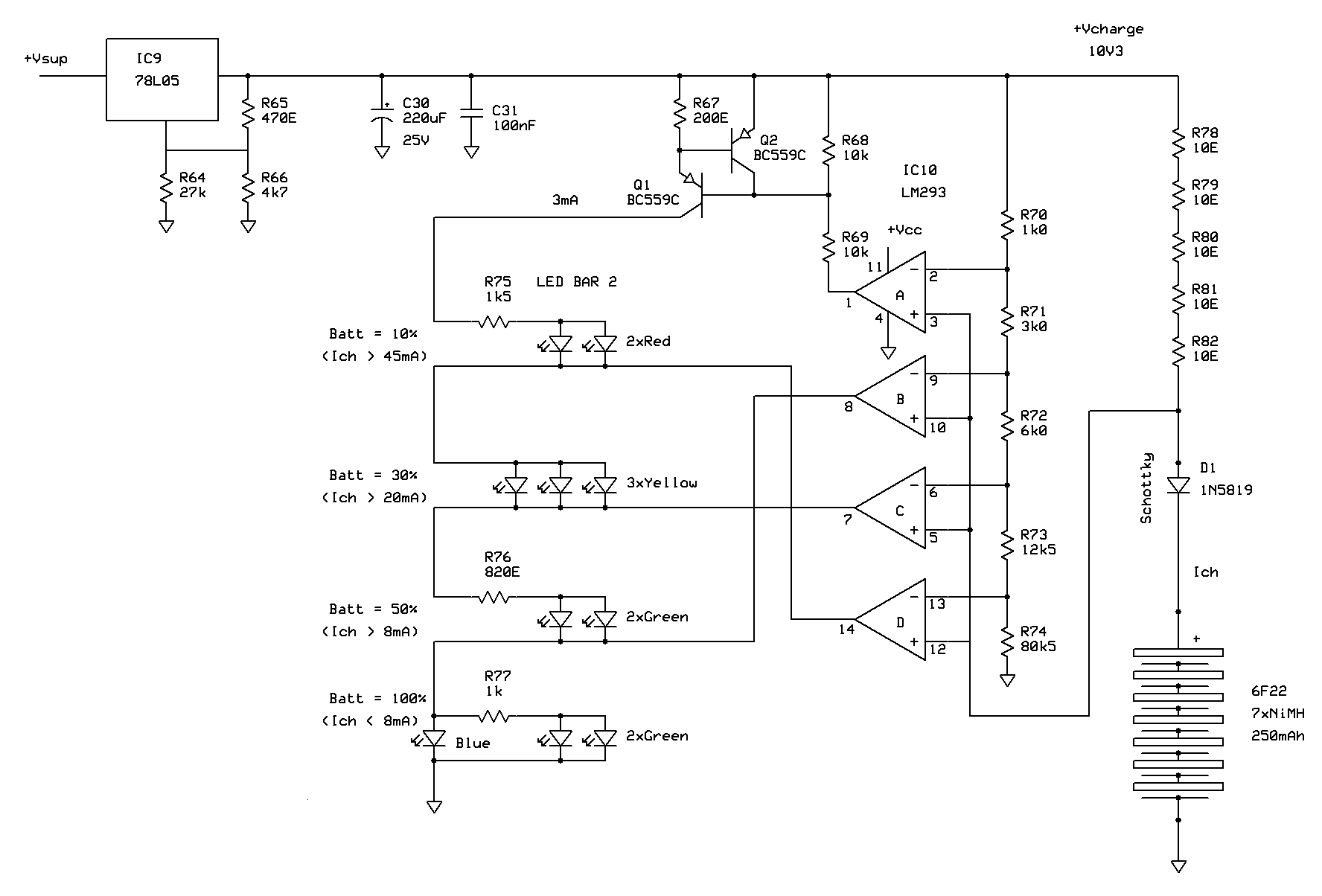
In order not to complicate things much further, we made a simple NiMH charger that gradually lowers the charging current as the charge level reaches 100%. Firstly the stabiliser voltage was chosen to almost match 10.2 volts of carefully measured fully charged battery voltage plus voltage drop on Schottky diode, and then the current limiting resistor R78...R82 was calculated so that current doesn't surpass the safe value when the battery is empty. As the battery charges, the two voltages approach each other and the current gradually drops down to a few miliamps which does no harm to the battery and keeps it fully charged indefinitely. Since voltage drop on the limiting resistor corresponds directly to the charging current, it means that it also provides a direct indication of the state of charge.

D1 is there to protect the charger circuit in case battery is left connected to it when the console is plugged out from the AC socket or turned off. One doesn't need to pull the battery out of the Mic Tx module because we put a DC connector on it and added a short corresponding charging cable to the console.
Visual indication of the state of charge is provided via a small LED-bar in rainbow colors. It turned out that making the surrounding indicator circuit was actually far more complicated than the one that actually charges the battery. Well... mostly because we opted for an unusual LED circuit in which consecutive LEDs/LED pairs are connected in series and the current for the whole chain is supplied by a single current source. Open collector voltage comparator outputs are then used to short-circuit some of the LEDs to GND, so that those that are not grounded indicate the state of the battery charge. This probably sounds simpler than it was to implement. In reality, reference voltages for the comparators needed to be calculated very precisely so that they indicate some meaningful thresholds like "50%". Then comparators needed to be arranged so that their outputs release consecutive LEDs in particular order from GND as the voltage drop on limiting resistor decreases... This tripply-doubly convolved negative logic was actually a bit of fun to deal with in its weird sense.
Matching the LED brightness proved to be tricky since blue and gren LEDs were way more efficient that yellow and red ones. Measuring the exact LED voltages and currents for matched brightness, and then calculating the resistors which must split the voltages and currents into approriate ladder branches was more than a thorough exercise in aplying Ohm's law and Kirchhoff's rules.
Although a tiny bit of skepticism about the correctness of the charging method was present at first, it turned out that as of time of writing this article the battery has been successfuly cycled daily more than a hundred times with no ill consequences. Because recharging Tx battery is as simple as connecting the module to a dedicated cable hanging from the mixing console, the battery hasn't been deep cycled a single time so far, so we suppose it will continue to live happily ever after. For a few years more, at least.

