Reference voltage
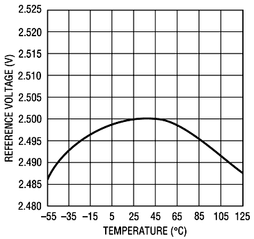
There are various reference voltage sources available on the market today. Some can be extremely stabile and quite expensive, but even the low cost ones give much more than one usually expects. We selected LM285 as a handy inexpensive chip with surprizingly good performance. in the diagram on the left is LM285 voltage dependence on ambient temperaure, as given in the component datasheet.
We can calculate from the graph that in the flat-top region between 25°C and 50°C the relative temperature coefficient is less than 1mV / 50°C = 0.00002/K. The sweet spot is around 38°C so that in the vicinity of that temperature there is essentialy no change in reference voltage. Thus if LM285 is kept at reasonably constant temperature around 38°C, we can expect its voltage to drift merely a few ppm, which suits our purpose perfectly well. If one wishes to eliminate even the tiniest possibility of voltage drift due to changing environmental conditions, LM285 can be placed inside the second miniature thermostating chamber such as the one built for the LED. We didn't feel real need to do so, and because of limited time available we decided to give the barenaked TO92 chip a few layers of thermo-insulating tights and give it a go.
LED current regulation
Once we have a stabile and constant voltage source, it is aesy to use an operational ampliifer and a transistor to convert voltage to tightly controlled current. In the circuit diagram below, that would be the purpose of U1A and Q6. But in addition to making the LED current constant, we also wanted to provide some sort of regulating it, so that various camera exposure times could be tested. In order to do so, we added a precise voltage divider formed around Q2 and Q3. They are governed by 8-bit PWM signal comming from the microcontroller and chop the reference voltage produced by LM285 so that DC LED current is between 0 and 0.5 mA. Those parts fill the top left quadrant of the diagram below; please click on it for full resolution image.

8-bit regulation didn't seem quite enough so we added a current chopper built with transistors Q4...Q5 and surrounding components. They are arranged to rapidly turn on and off, so that we are sure that they tightly follow another 8-bit PWM pulse train produced by the same microcontroller. When turned on, Q5 short-circuits the LED so some percentage of original Dc current produced by Q6 is prevented from being converned into light. All in all, this combined regulation enables LED current to be set by 7 nA step while at the same time being assured that ambint temperature has no influence on the number of photons produced.
Q7 is added as a simple switch that forces LED to glow much stronger with unregulated 10 mA current. The purpose of that is to enable testing of vignetting effects produced by camera shutter. Such measurements are typically done using strong light and short exposure times so that shutter transitions from fully shut to fully open and vice versa contribute appreciably to overall pixel exposure.
Monitoring light output
We wanted to have some means of monitoring the actual LED stability, but astronomical cameras under test could obviously not be used for that. So we decided to make a small light probe that is sensitive to very faint light typically used in measurements we planed, and that should have ~ an order of magnitude better temperature stabiity than the LED itself. This is not a simple task but we came up with an interesting solution.
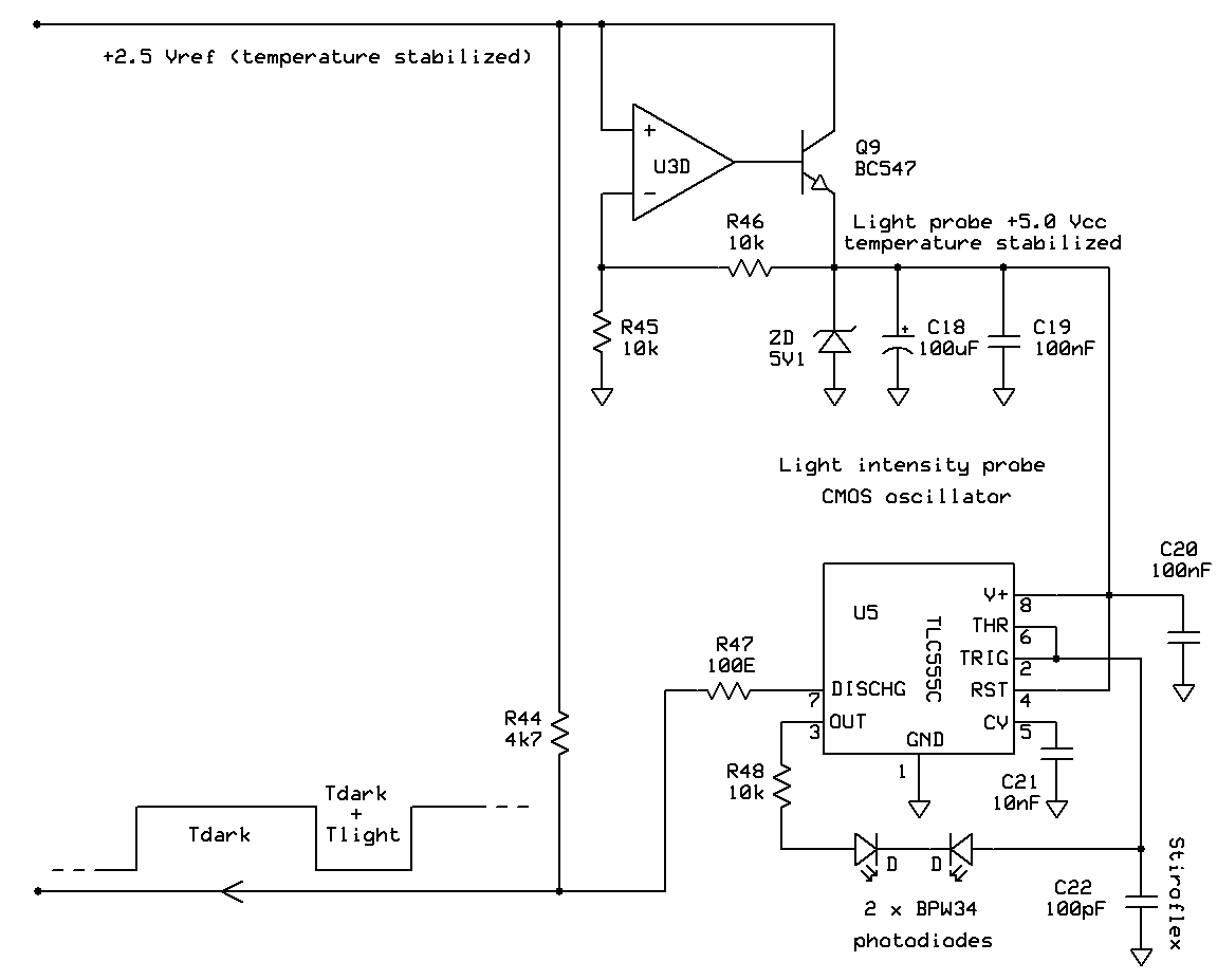
A pair of matched BPW34 photo diodes are connected in series with reverse polarity, and physically arranged butt-to-butt. One of them is positioned to look at the outside of a small mtal housing, while the other one is painted over by black acrylic paint and put into a dark paper mesh inside the same housing. The purpose of this arrangement is to subtract dark current of the "dark" photo diode residing inside the dark box from the light+dark current of the "active" photo diode looking outside. Not only does this make a hybrid sensor significantly less sensitive to temperature drifts, but it also makes it more sensitive to light, because now we can use arithmetics to monitor light currents way smaller then the diode dark current. In practice, if the two diodes are well matched, it turned out that it was possible to measure photo currents two orders of magnitude smaller than the active diode dark current!
A hybrid photo diode is connected into a circuit built around CMOS TLC555 astabile multivibrator, so that one of the photo diodes charges, while the other one discharges the reference capacitor. The higher the diode currents, the faster the capacitor chargs and discharges. CMOS pin input resistance is so high that it draws less than 5 pA which has no observable influence on measurements. Needless to say, traditional bipolar NE555 timer would be completely useless in this circuit. IC produces pulse train in which low level pulses correspond only to dark current of the passive diode, while high level pulses correspond to light+dark current of the active diode. Such PWM signal is easy to transmit over a few meter distance to the microcontroller which is perfectly suited for digital measuring of the signal-to-pause ratio to very high degree of precision and accuracy. In addition, PWM provides for signaling extremely wide dynamic range of light because one can measure duration of pulses arbitrarily short and long with the same degree of precision derived from the quartz crystal oscillator.
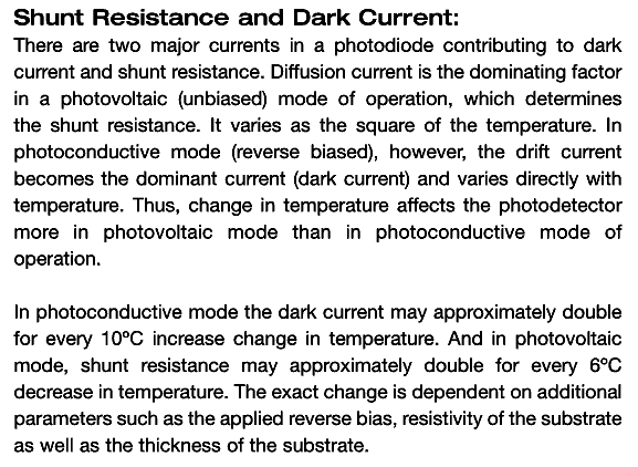
As for photo diode sensitivity to changes in temperature, theoretical considerations lead to an interesting conclusion that such devices are more immune in photo-conductive "current" mode of operation in comparison to "photo-voltaic" mode much more commonly used for measuring low levels of light. "Hybrid sensor" circuit described here uses both diodes in current mode to charge and discharge the reference capacitor. Readers interested in this topic can download the original article by clicking on the image on the right. Reference capacitor is a very special and nowadays rather hard to obtain Styroflex model which has the highest inherent temperature stability of all known capacitor types; such components were of great value in the era of analog AM broacast radio but those days are now long gone.
Auxiliary circuits
There were several input/output pins left on the microcontroller so we used them for measuring ambient temperature and providing a few On/Off in/out switches so that operator doesn't need to enter the room too often. Switches can be used for activating light blocking screens, diffusers etc. This also makes the measurements both more convenint and more reliable since room temperature changes is what we fight in the first place.
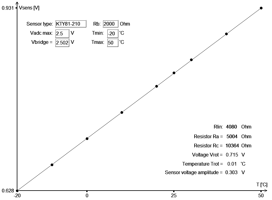
Component values of temperature probes were calculated using the
KTY sensor optimizer software found elsewhere on this web site.