Light source sommunicates with a lab PC using a virtual USB COM port. We prepared a simple Python script for controlling the light source and automatic data collection. For simplicity, we used a spreadsheet calculator from LibreOffice suite to analyse data and produce the diagrams.
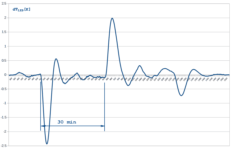
The first diagram represents the long term LED temperature response to step disturbances. It can be observed that integrating thermostat produces overshoots but eventually brings the temperature to its target value in the form of exponential decay. The process takes approximately 30 minutes which gives the lab operator enough time to smoke a cigar, chop the wood, milk the cows, feed the hungry, split the atom and finish other housekeeping duties between turning the power on and comencing the actual measurement procedure. Were the heating resistor string a bit less powerfull, overshoots wouldn't have appeared in the graph and measurements could have been starting sooner.
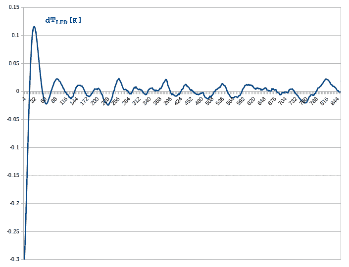
The second diagram is a zoom-in into the steady state of LED temperature regulation. A tick on the X-axis represents 5 seconds so the graph spans approximately an hour. RMS value of temperature variations is 0.016 K meaning that thermostating is performing OK. This level of LED temperature stability provides for 2E-5 of luminance stability, but there are other factors down the line that influence the final result.
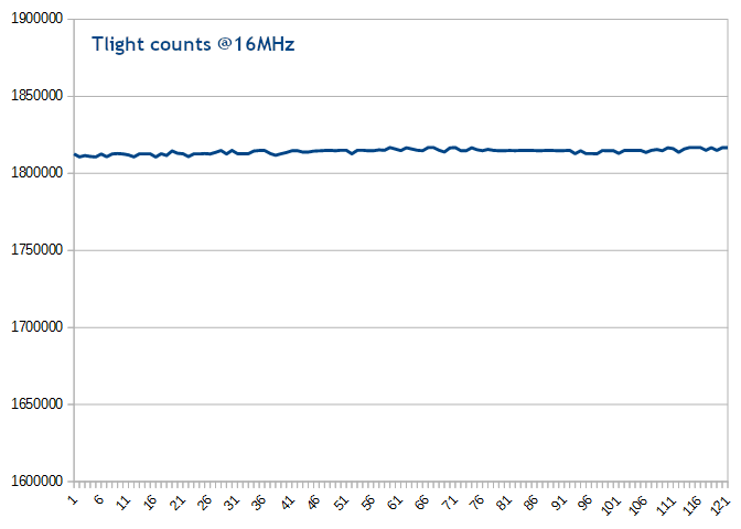
The last diagram represents relative LED luminance measured by the light probe described on the previous page. A tick on the X-axis equals 10 seconds, so the graph captures 20 minutes in total. RMS value is 8.8E-4 which is an order of magnitude higher than expected. We couldn't explain the discrepancy but we observed strong correlations between measured values of dark and light current pulse durations. The cause is most probably instability in reference voltage supplied to the light probe; there was not enough place inside the tiny metal housing (scrapped from an ancient AM IF transformer) to put both TLC555 and voltage regulator inside, so the latter was left outside. Thus we assume that electrical interferences are to blame and that LED light actually has better stability than we could verify using the simple probe.
Nevertheless, the device enabled the operators to verify a faulty astro camera which produced erratic behavior on the order of a few percent. That was enough of an argument to request a replacement from the producer. After gathering practical experience in this kind of electronic design and measurements, designing and producing a new improved version of the stabilized light source was considered for a few weeks but as often is the case, life went on.