Basic principles
The most important fact one should be aware of when constructing well behaving electronic equipmnet of any sort is that the dominant contributor to instability is temperature. In general, every electronic component responds to temperature variations by changing some of its working parameters. Some components are more sensitive than others, but very rare are such that are 100% immune to changes in ambient temperature. Therefore, by providing constant temperature environment for our device, we take a giant step forward towards the land of stability.
Another valuable fact is that essentially all electrical and physical paramaters can be referenced to voltage. In some cases that is easier to do than in others, but smart engineer will eventually find a way by constructing the appropriate electronic circuit to establish a connection between the parameter in focus and some reference voltage. In order to control the parameter, such electronic circuit/device would either "produce" the desired parameter out of the reference voltage, or would put the parameter under a negative feedback loop that compares it with the reference voltage. Knowing how valuable reference voltage sources are, it is no surprise that electronic industry provides a range of special perfectly stabilized reference voltage sources for constructors.
Finally, if "electronic environment" such as voltage, current, frequency etc. of an electronic component is kept constant, there is not much reason to expect changes in its output. In case of a light source, if voltage and current flowing through it is constant, being it a light bulb, an LED etc. we should expect that such source will produce the same number of photons each second.
So the basic logic is this:
- Select such type of light source that will be as little sensitive to temperature as possible.
- Construct a small chamber in which temperature will be tightly actively controlled and
put the light source in it. - Take care to keep the current flowing through the light source constant.
LED as a light source
One of the most well known facts about LEDs is that they are generally more eficient in producing light at low temperatures, but in this particular application that isn't of interest. We decided to use an LED as a light source in our device because LEDs are reasonably stabile with respect to temperature. LEDs are produced as complex semiconductor crystals that contain several various types of atoms; an exact atom mix leads to forming some particular "energy gap" for electrons flowing through such crystal, forcing them to radiate some particular color of light. Not only efficiency but also temperature stability of LEDs that produce different colors of light vary due to physical laws governing specific quantum efficiency of each LED type at given temperature. Astronomical cameras are sensitive to relatively broad band of light colors ranging from near UV to near IR so we had a lot of freedom in choosing LED with the lowest temperature coefficient of efficiency.
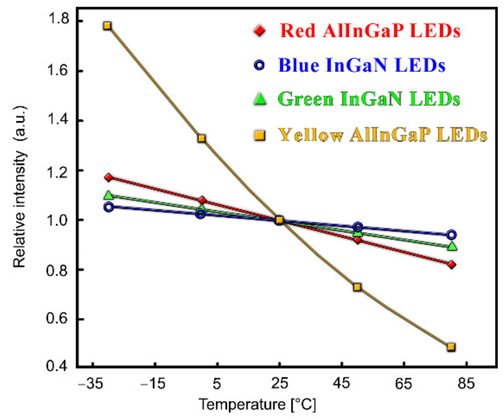
One of the most useful diagrams that we could rely on in making that decision is given on the right. It can be seen that the absolute worst LED color in terms of temperature stability is yellow because they produce the steepest line in the graph. In contrast, the most horizontal line belongs to the blue LED. Modern efficient white LEDs are made by covering blue LED core with yelow phosphorus material, and at the time of constructing the device it seemed as a great idea to use such white instead of a "bare" blue LED. The reason was that white light is broadband radiation that covers the entire visible region of spectrum and it is always a good idea to test a broadband receiver with a broadband signal - we weren't sure whether there was some undocumented quirky response of a particular camera to some particular narrowband part of the light spectrum. Cerium based yellow phosphorus is pretty stabile with respect to temperature and ageing so there were no reasons to suspect that wideband white LED would have tended to behave worse, or at least noticeably worse than a narrow-band blue one. In retrospect, selecting white instead of blue LED was not really necessary and could have made the stability a bit worse. If we decide to build a new version of the device, we will most probably pick a "raw" blue LED.
LED thermostat
It can be calculated from the graph above that relative temperature stability of a typical InGaN blue LED is -0.025 / 25K = -0.001/K. Such LED changes its efficiency by 0.1% if temperature of its crystal core for whatever reason drifts by 1 K i.e. 1°C. We aim at having light stability on the order of one hundredth of that, so consequently temperature variations of the LED during the measurement procedure should be kept below 0.01 K.
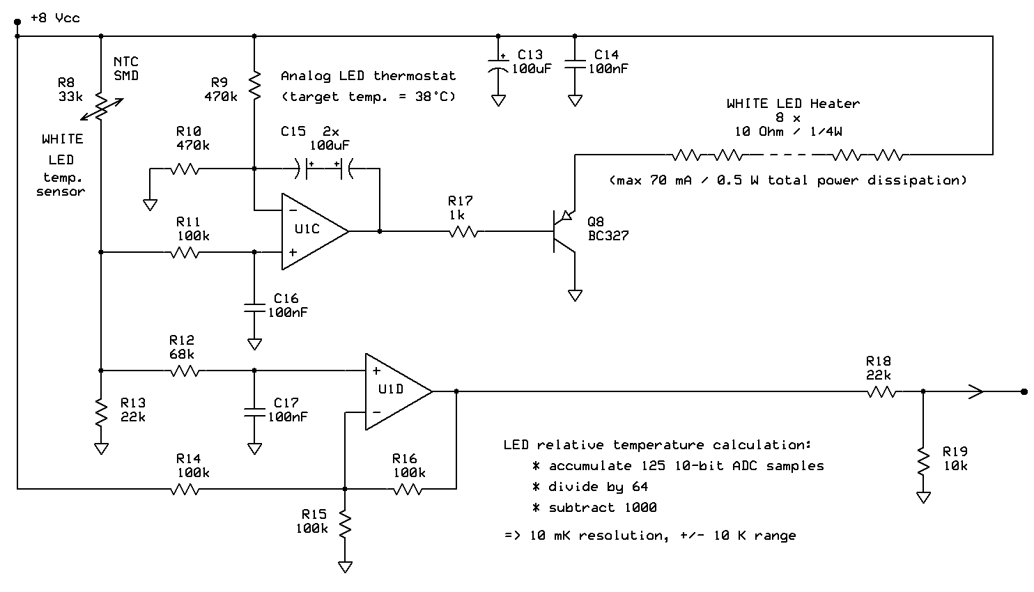
We constructed a simple analog circuit that autonomously regulates a tiny electric heater placed inside the housing of the LED so that temperature inside the housing is constant. The exact absolute temperature is again not important, the only obvious requirement being that it must be somewhat higher then the temperature of the ambient air. We decided to set it to ~ 40°C which is done by setting the ratio of NTC resistor R8 vs R13 to equal the ratio of R9 vs R10 at target temperature. As the time passes, integrator U1C pushes the difference between the actual and the target NTC temperature to infinitesimally small value. U1D uses NTC sensor voltage to measure its relative temperature drift and send the corresponding analog signal to one of the microcontroller ADC input pins.
Both NTC and heater resistors are connected to +Vcc because one of the LED pinc is also connected to it. This is done purposefully, so that a tiny SMD NTS can be soldered directly to one of the LED pins. That makes the sensor response to LED crystal temperature changes as rapid as possible. Heater resistors physically surround the LED housing in a zig-zag pattern formig a sort of a "crown" around it. This contraption is then surrounded by a layer of temperature insulating material, and put into a relatively massive metal housing. The whole set is then surrounded by yet another layer of temperature insulation. The purpose of all that is to prevent ambient temperature changes to influence LED temperature by forming a "low pass filter" structure for temperature flowing from the outside towards the LED. Wires connecting LED, NTC and heater resistors to the outside world are made if very thin wires which are firstly colied several times around the metal housing before they go to the outside world so that no back door "short circuit" tunnels for temperature waves lurking on the surface of the structure outer walls are formed.