LED headlight driver
Driver circuit in the diagram below is a
step-down or "Buck" DC-DC converter. It accepts power from a voltage source such as a stack of batteries or an AC-DC power supply unit and feeds the transformed lower DC voltage into a powerfull LED. The converter is self oscilating and voltage controlled. The basic concept is taken from the
RomanBlack web page, and we added a few upgrades to it. Similar circuits operate in professional devices such as life saving defibrilators for decades, so there is no "clear!" reason to worry about the reliability of the scheme. There are no hard-to-find components in the circuit and the whole thing shouldn't cost more than a dollar or two to build. Yet its efficiency is typically above 90%.

There are two most important components in the diagram: voltage comparator U1 and MOSFET transistor Q3.
Voltage comparator U1 performs two roles - it precisely regulates DC voltage on the output LED, while at
the same time it uses small variations in that voltage in order to establish a self oscillating regime.
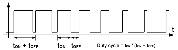
At the output of U1, there is a train of pulses which is used to control the MOSFET. DC voltage regulation is achieved by varying an inverse duty cycle of the pulse train: if there are more spaces than marks, output voltage rises, and vice versa. Varying pulse train duty cycle is commonly known as pulse width modulation, or PWM for short. Inversion comes from the fact that Q3 MOSFET is of P-type, which means that it turns on if voltage on its gate (G) is negative with respect to its source (S).
In order to achieve very high efficiency of power conversion, it is essential to avoid the so called transitional losses which practically means to switch Q3 on and off as abruptly as possible. Output curent from U1 is sufficient for fast switching of Q3 on, but for fast switching it off, an auxiliary circuit formed around Q2 is added. If everything else is built with certain care, meaning that traces and component leads are as short as possible and the coil is of high enough quality so that it has no unnecessary inductive or resistive losses, this converter circuit is able to transfer power from batteries to LED with more than 90% overall efficiency. The remaining losses can be mostly accredited to unavoidable thermal dissipation in Schottky diode D1. This is essentially as far as standard DC-DC conversion schemes go; a few percent higher efficiency can be achieved by using expensive dedicated driver integrated circuits, additional MOSFETs instead of Schottky diode etc. As most experienced DC-DC converter designers would admit, in practice that means a lot more money and headache for not really gaining that much.