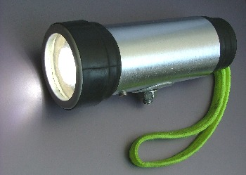
Side view of the second (*) headlamp prototype. Headlamp mounting screw is visible at the bottom of the lamp while the fluorescent carrying strap is hanging down from the lamp backside. Lamp body is made of an empty aluminium pressure bottle tank - aluminium doesn't rust which makes the lamp water resistant. Aluminium is also one of the best heat conducting materials (diamond is the best, but still pretty expensive) so the lamp housing functions as a passive LED cooler, too. Although there are no cooler ribs, air flow around the headlamp is more than sufficient to provide excellent LED cooling.
In front of the mounting screw, there is a standard 3,5mm MONO headphones connector used for charging the batteries (NiMH accumlators) built into the lamp without taking them out of the housing. The connector is mounted at the bottom of the lamp housing so despite no rubber plugs are being used, rain drops can't enter the lamp. The same connector can provide current limited to 20mA for powering small external devices on the field - for example a small LED flasher used for locating the lamp inside a dark camping tent.
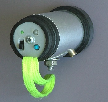
Backside view of the same headlamp prototype. This lamp has two switches and two signalling LEDs. The one with a black slider at the bottom-left side turns the lamp on and off. A blue push button toggle switch sets the LED power - when in the "down" position, LED works with the full power. Actually, with 133% of the power rated in its datasheet as this doesn't shorten the lamp lifespan noticeably in this particular application.
Green LED at the top-left position signals that the lamp is on. This turned out to be a very useful feature as it is due to environmental conditions sometimes hard for a cyclist to estimate whether the lamp is actually on - for example is the lamp is used as a daylight driving light on a foggy day. Red LED to the right signals the drained batteries. It is set to light up if there is less than 1/2 hour of energy remaining in the cells, if the lamp is set to low power. So, if the red LED is lit, a cyclist should immediately lower the lamp power if it was set to high power, in order to safely return home. Fortunately, 2300mAh NiMH accumulators built into the lamp provide more than 7 hours of continual lamp operation so this warning LED rarely turns on.
Cinch connector at the bottom of the lamp is used for attaching a flashing push-button momentary switch. This is yet one more feature not documented in the original lamp circuit diagram, used for giving notty car drivers a warning that a cyclist is present on the road. While being held down continually, the switch activates a simple astable multivibrator circuit set to approximately 5 Hz / 50% duty ratio which in turn powers on the rest of the lamp electronics producing amazingly bright and annoying flashes which drivers simply can't ignore.
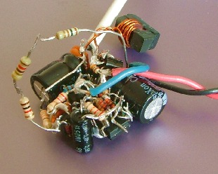
A glimpse at the actual converter implementation built into this lamp prototype. Not pretty at the first look, but compact enough to make ist maker proud :) The rats nest technique used here is much slower and trickier than standard PCB mounting when gathering circuit components togehter, but it provides a flexibility when adjusting the circuit topology and choosing exact component values in the development phase. Such circuits are usually mechanically stable enough to be built into the prototypes. So don't you frown - designer engineers love handling ugly bugs like this one.
* The reason this prototype is being referred to as "the second" is that the first one has been stolen together with the bicycle it was mounted on. Its designer - then acting as a human test subject in the headlamp project - stopped for a moment and parked the bike in front of an electronic components shop in order to buy a pair of red LEDs for another bike project... A minute later, while happily exiting the shop with a pair of fancy LEDs in his hand, he spotted 1/2 cubic meter of fresh air instead of his bike. Despite a torrent of curses, neither bike nor the headlamp ever returned to their owner.
Morals of this story:
1) High power LED bicycle headlamps are too shiny and whistly for burglars to ignore. Should one not intend to park their bike inside a sturdily built and well guarded concrete bunker, one should provide a way for quick and easy dismounting of the lamp. This is the reason the second lamp prototype has a big screw attached to its bottom.
2) As no competitive products have been observed on the regional electronic products market since the accident, LP assumes that "rats nest" DIY technique provided a means of protecting the circuit design against possible reverse engineering attempts. As some readers skilled in DIY might be aware of, drawing the circuit diagram using an existing PCB is hard enough, but doing so using a Gordy knot like this one is pretty much an impossible task for human brain. One migh think that perhaps an advanced 3D analysing Borg implant might help its owner to perform better, but a collective representative attempting that will in fact introduce
fatal instabilities into the Hive consciousness as RD circuits often contain surplus parts, single-pin remnants of fizzled-out components and simmilar stuff making them seemingly impossible to implement in this world and to work at all. Any higher intelligence would simply go grapefruits analysing it! So sleep well and fear not of space invasion - numerous highly trained proffesionals constantly introduce alien traps like this one into the environment. Even more such defensive efforts are put into practice in software industry and global economics...