Basic LED properties
Firstly, let's straighten a few facts on LEDs. LED is a short for Light Emitting Diode.
The term diode means that there is a single P-N junction in each LED, which is simply a contact
between two similar but slightly different pieces of cristaline materials. When electricity
flows through the junction, energy of electrons is converted into photons i.e. visible light. Nice.
Now, some more facts on the diode part of the short. As any other type od diode, electrical
curent can flow through LEDs in only a single direction. This means that we need to use direct curent
i.e. direct voltage to power them. Examples of such power sources are batteries, DC plugs etc.
of which we want to use batteries, and preferrably rechargeable ones. When diodes are of concern,
the most important bit of data for designing electrical circuits incorporating them is the maximal
alowable amount of curent. If we put too much current into a diode, it will die. Therefore we definitely
want to limit the curent flowing through an LED.
When designing circuits with diodes, engineers use the so called U-I diagram to estimate
curent and voltage that will be appropriate for particular type of diodes. It goes the same with LEDs.
The next illustration is a typical U-I diagram of a powerfull white LED.
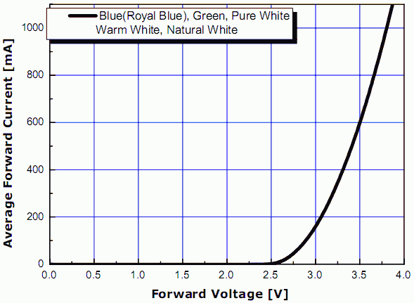
The diagram relates the ammount of curent that flows through the diode with the voltage set on its
contacts. An important fact to observe is that we do not need to limit the curent directly, but instead
we can construct a regulating circuit so that it limits the voltage on the diode and curent will be
set automatically by the diode itself.
Voltage vs curent regulators
For the purpose of powering LEDs, industry mainly uses curent regulating circuits instead of voltage
regulating ones. The reason for this is steepness of the LED U-I diagram - a careful reader can observe
that even minor changes in LED voltage (U) easily lead to dramatic cnahges in LED curent (I). For example,
in point B on the diagram above, LED voltage is set to only 70mV i.e. 5% above that in point A but curent
in point B is as much as 50% higher than that in A. Therefore one can either regulate LED curent directly,
or they need to be very careful with voltage regulators in order not to harm precious LEDs. For circuits
produced in series of thousands, the former method is clearly superior, but for experimental DIY models
the later can be much more rewarding.
But why bother? Why simply not use a standard curent regulator? The reason is that voltage regulating LED
powering circuits can operate with higher efficiencies, saving up to 10% of energy from the batteries.
Despite that might not seem much, it can be shown that in case of an LED bicycle headlight it easily
translates to as much as half an hour of headlight operation.
To resume, on the next page a circuit diagram of LED powering circuit in the form of a voltage regulator
will be shown. The circuit is constructed carefully so that it keeps LED curent well within alowable limits
while at the same time it doesn't waste energy from batteries.