Low noise JFETs
As the purpose of this device is listening to and/or recording of faint distant sounds, it is necesssary to equip it with a high quality low noise preamplifier. Designing professionally such circuits is a form of art on its own, but freelance experimenting can't hurt in DIY world. This was an ideal opportunity for the author of this text to try making anything useful with somewhat exotic components called junction field effect transistors (JFET). Historically speaking, those actially predate now ubiqutous bipolar (NPN and PNP) transistors. Despite having noticeably worse operating characteristics in most aspects, they still posess a few distinctive advantages when used in specific applications.
The most important advantage of JFETs is inherently lower internal noise they generate compared to bipolar counterparts. The reason is that in JFETs current flows only deeply inside the component semiconductor chip and not over its surface such as is partially the case in bipolar transistors and predominantly the case in MOSFETs. Exact explanation of why "internal" current flow generates less noise requires dealing with quantum mechanics but in essence, this is caused by electrons and holes bumping much less into various semiconductor material annomalies on their trip from the input to the output transistor electrode. The smoother the flow - the less excess noise generated.
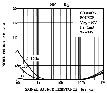
JFET transistors perform exceptionally well in terms of noise when signal source impendance is sufficiently high. In the microphone circuit we discuss, that impedance is actually the ohmic value of the microphone polarising resistor R1. Most JFETs are quite fine but some parts are unbelievably good. One such gem is 2SK170 produced by Toshiba. An interesting diagram given on the left can be found in its datasheet, stating that at drain DC current of 1mA and input impedance between 2 kΩ and 75 kΩ, this device introduces virtually no noise into the audio signal! The same datasheet specifies that under the given conditions, 2SK170 generates as little as 0.9nv/Hz
1/2 equivalent input noise voltage, much less compared to even the best operational amplifiers of acceptable cost.
There is yet another advantage of using JFETs as active components in preamplifier input stages - contrary to bipolar transistors, they don't perform hard clipping of the signal if strong impulses suddenly apper in it. Due to very high acoustical gain of the parabolic antenna, this is something we must count on. Thanks to relatively soft JFET signal clipping, listener's ear drums will not be blown out that easily as if a bipolar transistor was used in place of a JFET.

The above circuit diagram is the complete electronics used in the first LP parabolic microphone prothotype with which all sound recordings that can be found on the last page of this article were made. The preamplifier subcircuit is formed around low noise JFET transistor 2SK170, while post-amplification and signal shaping is done by one half of TL072 double low noise operational amplifier. The other half of the same integrated circuit together with a few small signal bipolar transistors forms the output power amplifier. Because of using a sound focusing parabolic dish, signal equalisation is a bit different than what one might expect. The next page of this article explains this in details.