Shaping the focused sounds
There is an intersting aspect of using parabolic focusing dishes for collecting distant sounds - the higher the frequency of sounds, the higher the dish gain. To understand why this is so, we should start thinking of the dish as of an antenna. Instead of gathering electromagnetic waves, it collects sound waves but the mathematics involved is the same.
Let's imagine for a moment enjoying a ride with a gang of sound waves running up against our antenna. How do various waves "measure" antenna dimensions and correspondingly its focusing properties? To answer this, we need to accept that waves don't "know" anything about imperial or metric units; all they are actually aware of is their own wavelength. The longer the wavelength, the smaller the antenna looks to a wave. The biggest waves i.e. those with very long wavelengths don't even notice tiny-mini antennas on their way - a wave spanning 100 meters should not worry about bumping into an antenna 0,5 m wide of any shape, as a 10 ton truck would not bother with whether it run over a prawn, a praying mantis or a mantis shrimp. It simply goes over (around) it and carries on with the ride. Those waves with shorter wavelengths do notice that something got in their way, but there is hardly any directionality of their paths after the collision with objects having dimensions simmilar to their own. Such waves simply disperse in all directions after the collision as cars usually do after encountering another car or a moose. In other words, no particular focusing takes place. But those waves with even shorter wavelengths do notice something interesting. Depending on which part of the antenna they bumped into, they bounce off in precisely controlled manners. A tiny waveleth bouncing off the parabolic antenna center will simply go straight back, thumping after a fraction of a second into the microphone. Another one will, after hitting a point somewhat more distant from the center, bounce at an angle equal to the incident one and, after a short period of time, hit the microphone. And it goes on. So all such waves, no matter which part of the antenna they hit, inevitably fall into the microphone. Now that's focusing!
What does the mathematics say about this phenomenon? Without diving into formulas too deeply, math says that attainable antenna focusing power depends on the ratio of antenna dimensions and wavelenght in interest: D/L, where D is antenna dimension and L is wavelength, both expressed in the same units. The greater the ratio i.e. the longer the antenna dimension in comparison to the wavelength, the stronger the focusing can be. Note that there are other factors in the complete antenna gain formula but all we are interested in at the moment is that there is a factor "D/L" somewhere in it. But here is yet another interesting point - the above formula deals with a single space dimension. Therefore, antenna focusing power depends on the ratio linearly as stated above if wave focusing takes place only in a single spaceal dimension, for example if an antenna takes shape of a long hollow tube cut in half lenghtwise. But a paraboloid dish can be taught of as a kind of a hollow tube cut in half and then folded up again in another perpendicular dimension - it focuses waves not in one but instead in two dimensions simultaneously. The overall focusing power is therefore the product of independant focusing processes in two perpendicular dimensions i.e. in antenna length and width. Expressing this mathematically, we say that the focusing power of a paraboloid antenna depends on the square of the ratio mentioned earlier: (D/L)2. Another form of expressing the same phenomenon, to which electronic engineers are generally more familiar, is to say that parabolic antenna focusing gain has +12dB/oct rise over the frequency spectrum.
This has some unusual and interesting consequences. Sounds collected by a parabolic antenna and amplified directly without any corrections would seem very unnatural to human ears. There would be not much if any low frequency sounds to discern, while those high frequency ones would be overly strong and unbareably annoying to listen to. What should we do about this? Obviously, some kind of high frequency attenuation must be put into practice. This is fortunately easy to do using standard audio frequency filters. A simple RC "low-pass" filter corrects audio spectrum by -6dB/oct, so we should use two of them in series. Note that high frequency cutting is something usually being done outside the frequency spectrum in interest, but in this application it should take place over the whole audio spectrum. In the circuit diagram given on the previous page, this is done by components 15nF near the microphone and 22nF, 3k3 and 47nF near the lower half of TL072 operational amplifier. It doesn't actually matter where those corrections take place, but be aware that their position influences the overall system performance in terms of noise - if signal attenuation is done too early in the amplifier chain, it might easily render high frequency signals too faint compared to inherent internal noise of those amplifiers that follow, and the performance would be quite poor. As high frequency sounds usually have rather small amplitudes, there is hardly any danger of them saturating the amplifiers, so corrective filtering is best to be done close to the final output power amplifier stage rather than to some of the stages in the preamplifier section.
From the standpoint of a designer engineer, the necessity to attenuate high frequencies can be taught of as a struck of luck. It is well known that subjective human perception of the quality of an audio system depends predominantly on its performance in higher portions of audio frequency spectrum - the less hiss and distortions, the better the device quality appears to be. By attenuating high frequencies, not only unwanted frequency distortions but overall system processing noise gets cut down as well, practically forcing parabolic microphone amplifier circuit to present itself as an unusually high quality peace of equippment!
Automatic sound level control
In any amplifier system which has high processing gain, it is often desirable to have some kind of automatic gain control. The purpose of this automatics is twofold - it not merely equalises levels of various signals to the same optimal value, but as well prevents stonger signals to overload the rest of the processing stages that follow the premaplifier in the signal processing chain. This project would be an ideal testbed for experimenting with ALC circuits but unfortunately the author did not have enough spare time to do it.
There are many possible methods for implementing analog audio ALC. Some of the simplest ones utilyse the property of active semiconductor components such as bipolar and JFET transistors to vary their AC gain due to changes in DC biasing current or voltage. Adjusting everything in such circuits to work as desired is usually not the easiest task to do, but the results can be pretty satisfying.
There are also analog integrated circuits on the market such as
LM13700 which expose dedicated DC inputs using which the gain of their internal amplifiers can be dynamically adjusted. Such ICs are versatile and indeed very useful in analog signal processing but to form an effective ALC subcircuit, they require quite a bit of additional components configured so that they extract audio level information from the sound signal, which is then used to continually set the appropriate circuit gain. A studio quality sound processor would probably incorporate this kind of sophistication together with audio compressors etc. But that kind of advanced electronics would neither be easy to set up nor would it be easily portable.
Fortunately, there are still out there some inexpensive specialised integrated circuits aimed at controlling the gain automatically in now obsolete tape recorders. All they need is a simple RC filter to set the time constant of their internal ALC. If you still haven't done any experimenting with those, it's well worth a try.
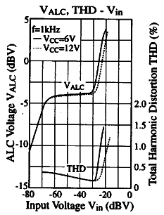
AN7312 is a fine representative of this chip family and its performance in terms of controlling audio signal levels is given in the diagram on the right. It can be observed that for input signals ranging from -70dBV to -30dBV (i.e. 40 dB range), there is hardly any change in output signal level. For those not familiar with dB units, 40dB is equal to the difference between the two signal amplitudes of one hundred times! The author of this article would be very happy to hear from courageous users who have tried any of the techniques mentioned here in their diabolic mikes.